Tyshevych B. L., Orlov M. V.
MATRIX frequency converters
in electric drives with synchronous motors
In this
article are analysed features of a matrix-using frequency converter with an
electric induction motor, comparing with a traditional bridge frequency
converter. Investigated are benefits of a matrix-using frequency converter
during the work with correction for determining the exact position of the rotor
synchronous motor.
Key words: electric drive; synchronous motor with permanent
magnets; matrix frequency converter; rotor position correction.
Introduction. A synchronous motor is an electric machine, rotor
speed of which is equal to the rotation frequency of the magnetic field. Low
power (10 kW) engines are mainly made of a permanent magnet rotor (SMPM).
Currently, this type of an engine is the most promising for the electric drive.
They have several advantages: high energy performance (90 % efficiency);
smaller weight and size; wide range of rotation frequency; high overload
capacity for the moment; long life, and high reliability.
The main advantage of the synchronous
motor is the possibility of obtaining the best mode for the reactive energy. The
synchronous motor can run without consuming and not giving reactive power to
the grid, with power factor equal to one. In these conditions,
engine load network only by active current.
Calculateing
the coordinates of the rotor by conventional converters will be difficult and
not accurate. Therefore, in recent years, much attention has been paid to the
development of a matrix frequency converter (MFC) that is a structurally direct
AC-AC converter and is capable of generating voltage with almost ideal form, and
free of flaws tension that bridge converters have .
The purpose and objectives. Exploration of the peculiarities of
an electric SMPM MFC using. Comparison of MFC
traditional bridge converters. Determination of how increased accuracy
estimation coordinates of the rotor in SMPM with the help of
MFC.
Research results.
The application of the MFC can
solve pressing problems. The MFC’s simple design – three-phase power supply
connected to the engine via a bidirectional semiconductor switch matrix (Figure
1). These switches’ orderly operation voltage and the frequency output of the
engine can be regulate1d with high precision.
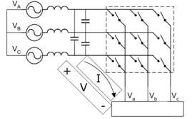
а b
Fig. 1. MFC: а – block diagram;
b – circuit connection switches
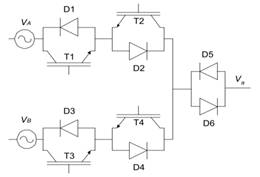
The matrix
converter belongs to a group of frequency converters with direct connection.
Each switch has two field-effect transistors with an insulated gate (IGBT). In
the power converter circuit IGBT 18 is used. IGBT power switches are connected
in such a way that the energy can rise to the engine as well as play back to
the grid during braking and recovery.
To determine the exact position of
the rotor in SMPM nonsensory management, a correction method that gives good
results when using the MFC is proposed. The disadvantage of the method is the
need for a productive microprocessor technology and conducting bench tests.
The method involves the separation
(filtering) of harmonic components of low order - current Ialfa, Ibeta that
determine the rotor’s position. The value of current Ialfa, Ibeta is determined
through filtering currents Iα, Iβ of the three-phase
transition to the two-phase coordinate system (Clarke transformation).
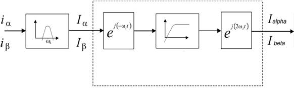
Fig. 2. Block diagram of Ialfa, Ibeta
determination
Finally, the system for
determination of rotor’s position computing using signal processing is
presented in Figure 3. Addressing data have been entered into the database on
the stand, carried by the value of current isq
*, for a variable-phase coordinate system, and an improved rotor position r.
For these values ΔIalfa,
ΔIbeta are selected, being
filtered; a transition to the definition of an intermediate estimated rotor
position δ and phase shift correction are carried out, taking into account
the saturation current determined by the moment isq *. After all the procedures we can determine the
rotor position.
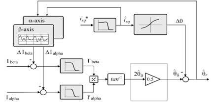
Fig. 3. Block diagram of the sequence of operations to
determine the exact position of the rotor.
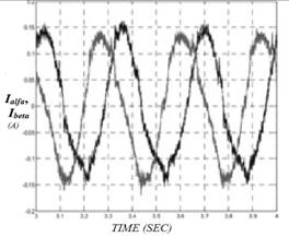
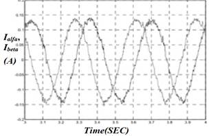
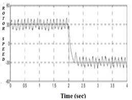
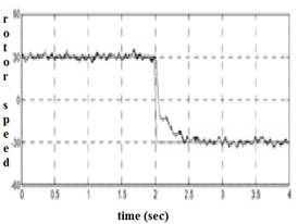
When
studies are obtained, the current schedule changes Ialfa, Ibeta determining the
rotor’s position and graphs change the rotor’s speed SMPM (Figure 6). As seen
from the graphs, after applying the correction,
significantly increases the accuracy of the speed regulation rotor.
а
b
c
d
Fig. 4. Graphic of currents
changing Ialfa, Ibeta and the rotor’s speed:
a, b - without rotor position adjustment; c, d – with application of the
rotor’s correct position.
Conclusion
Compared
to a traditional bridge frequency converter, the use of the electric BFC SDPM offers advantages in accuracy of determination
of the rotor’s position, and consequently, improvement of the regulation
quality of a wide range of speed. The BFC’s main
advantage is the minimization of nonlinear characteristics, the main of which
is the "failures" of voltage and current, resulting in their
non-sinusoidal shape. As seen from the results, with the MPCH method of
correcting the estimated position of the rotor, the quality of the electric
SMPM’s speed control increases.