Vashchenko M. A.
National
Technical University of Ukraine "Igor Sikorsky Kyiv Polytechnic Institute", Ukraine
Studying the electrical drive, we can often hear the phrase an AC engine
with an asynchronous-valve cascade. The AVC is easily included in
the system of automatical the monitoring of the production process. This stage
significantly increases interest in electrical drives, capable of engine speed monitoring.
It is used in frame for high-power fans, pumps and compressors. One of the main
advantages of this stage is the reduction of electricity intake. That is due to
the fact that in large enterprises energy saving is one of the most grave criteria.
Another big advantage is advance of the qualitative of products achieved by the
energy recuperation slip of the AC engine.
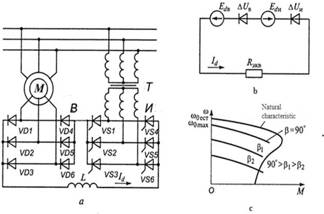 Fig. 1. The electrical outline (a), the outline
for replacing the rectified current outline (b), the mechanical characteristics
(c)
Fig. 1. The electrical outline (a), the outline
for replacing the rectified current outline (b), the mechanical characteristics
(c)
The figure
shows a diagram of the AVC that provides the engine operation. If we look at
the specifications, we will see that the speed lower than the synchronous
engine’s speed is continuously adjustable down to the natural characteristics. If
you look at the startup circuit, you will see an equivalent resistor.
In addition, the
converter used at the valve phase is
only rated for power proportion to this control range. At the same time, in group
with frequency control, the converter participates in the creation of a magnetic
flow, and when designing it, it is necessary to take into account the total
power of the drive.
The simplest
scheme of the valve stage is a outline with an intermediate DC circuit and a
gate converter. In the AVC, the energy of sliding is first converted into immediate
current energy, and then by the inverter UZ2 into the AC energy of a fixed
frequency. The transformer T is designed to match the output voltage of the
inverter with the mains voltage. To control the speed of the AVC, it is
necessary to change the value of the inverter’s electromotive force on the DC
side by changing the opening angle of the thyristors (b).
In this
electrical drive, with a simple regulating device, a wide speed range and torque
monitoring is provided for the engine, and high energy values are achieved by
transferring energy from the motor rotor outline to the capacity supply
network.
The energy
given by the cascade pollutes the network with higher harmonics, which
adversely affect the work of a number of consumers. And, finally, the largest
capital and estimated costs required for the equipment for driving the cooling fans
according to the AVC scheme exclude its request in the coming years to the
drives of the cooling fans.
Thus, in the
proposed AVC, a wide speed range and torque monitoring is provided, with the
motor's sliding energy from the rotor circuit being returned to the alternate
current outline across an optocoupler bridge converter operating in an inverter
mode, which provides energy saving. The proposed monitoring system is simple and reliable; mechanical characteristics are
favorable for hoisting and transport mechanisms.
One of the
biggest drawbacks of this stage is its low the force factor and the cost of the
converter that increases the cost of the drive. In terms of amount and value of
the equipment, there is a certain relationship. The greater the volume, the
greater the cost of the equipment, so advantageous to use the
asynchronous-valve cascade with little regulation of the engine speed.
The asynchronous-valve
cascade provides the following types of protection and interlocks from:
- external and
internal short outlines;
- inadmissible
by magnitude and duration of the overload currents of the power outline
elements and the powered motors (time-current protection);
- violation of
the cooling system;
- increased and
reduced supply voltage;
- exceeding the
speed of the engine;
- an
unacceptable reduction in the tension of own needs;
- malfunction
of power supplies;
- blocking the
activation when there are emergency and warning signals.
The applied
control scheme for regulating the speed of movement is based on a change in the
additional resistance in the rotor circuit, which causes large losses of the electric
power consumed by heating the resistors and a low range of shaft speed
regulation.
Mathematical
models of open and closed systems of the AVC
allow conduction of the research of dynamic processes and static
characteristics of the electrical drive under various constructions of the
power part and automatical monitoring systems.
A system for
starting an asynchronously valve stage is designed to smoothly control the
voltage at the output of a controlled rectifier connected to the windings of
the motor rotor as a function of the electromotive force of the rotor winding,
which expands the functionality of the asynchronously valve stage. Thus, using
the AVC by different companies, we can
achieve energy savings and get an manageable electrical drive.